 English
 中文简体
-
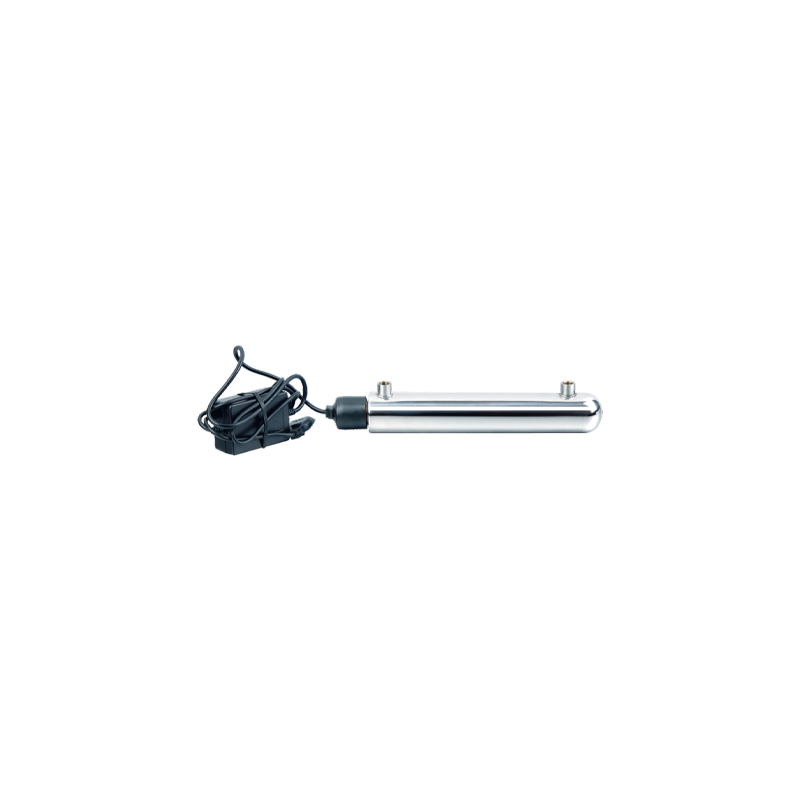 UV11W High-efficiency Intelligent UV Water Sterilizer Cat:Ultraviolet Water Sterilizer
The UV11W High-efficiency Intelligent UV Water Sterilizer is an advanced water purification system that offers convenience and reliability. This steri...
See Details -
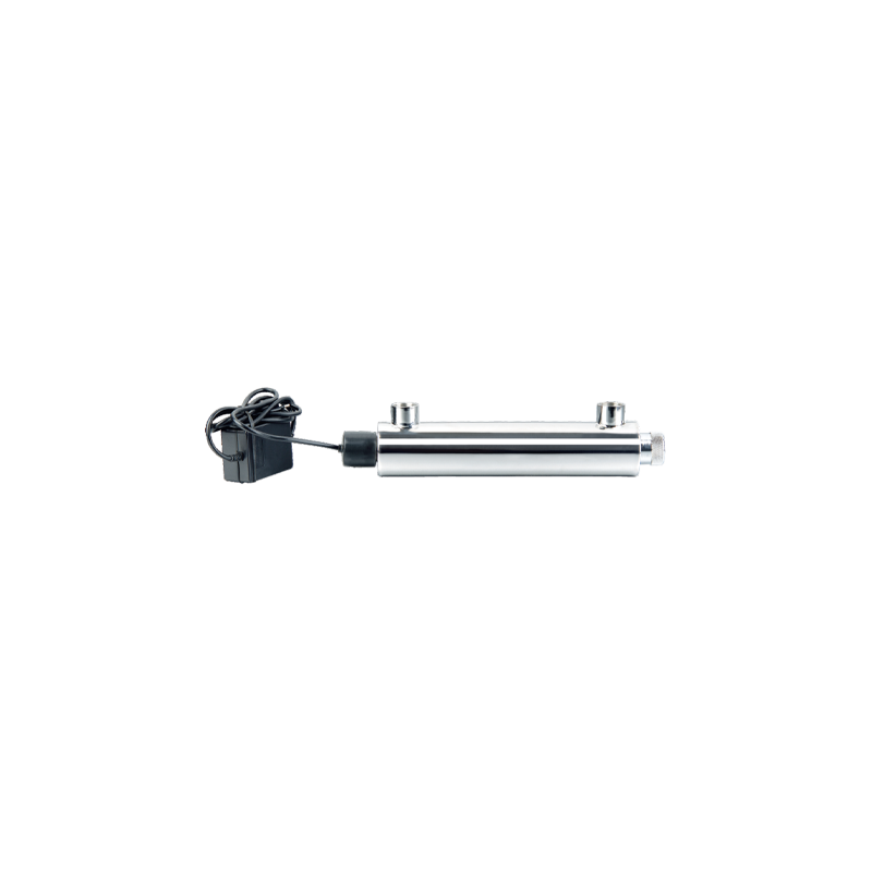 UV16W-A Household Stainless Steel UV Water Sterilizer Cat:Ultraviolet Water Sterilizer
The UV16W-A Household Stainless Steel UV Water Sterilizer is an innovative solution for ensuring safe and pure water in your home. Designed with durab...
See Details -
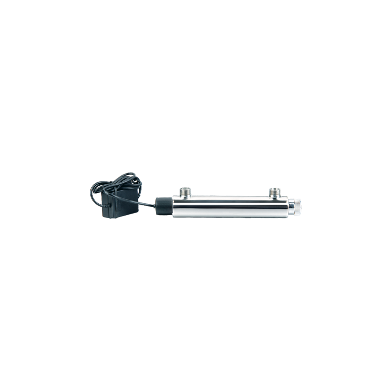 UV16W-B 304 Stainless Steel Water Purifier Ultraviolet Water Sterilizer Cat:Ultraviolet Water Sterilizer
UV16W-B 304 Stainless Steel Water Purifier Ultraviolet Water Sterilizer is an efficient water treatment equipment based on advanced ultraviolet disinf...
See Details -
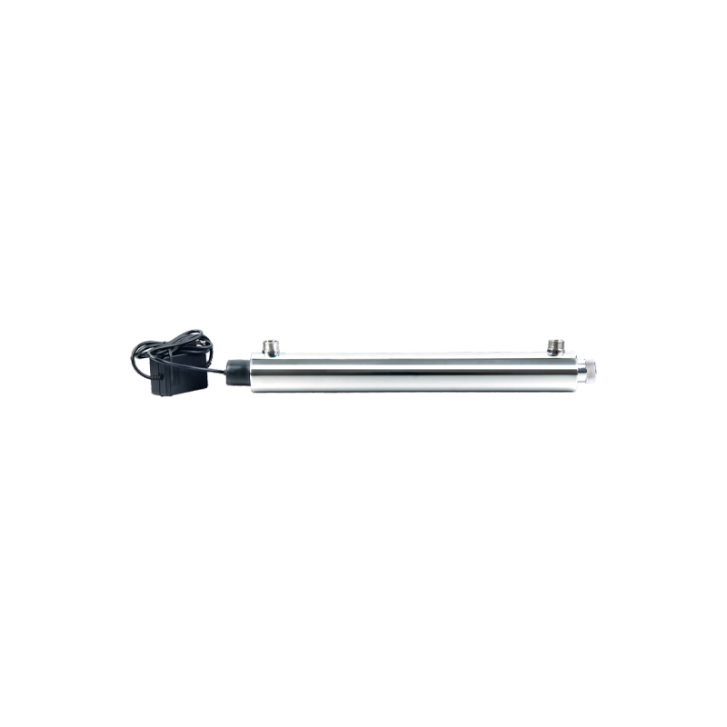 UV25W Stainless Steel Ultrafiltration Pre-Filtration UV Sterilizers For Water Cat:Ultraviolet Water Sterilizer
UV25W Stainless Steel Ultrafiltration Pre-Filtration UV Sterilizers For Water uses high-quality stainless steel materials, which have superb corrosion...
See Details -
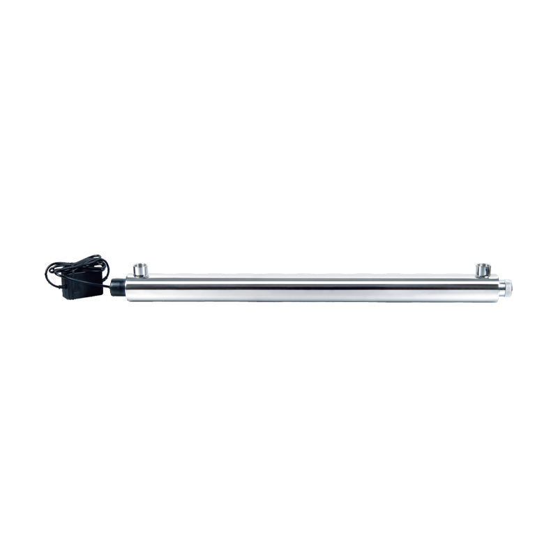 UV30W-55W Automatic Ultraviolet Sterilizer UV Filtration For Drinking Water Cat:Ultraviolet Water Sterilizer
The core advantage of UV30W-55W Automatic Ultraviolet Sterilizer UV Filtration For Drinking Water lies in its efficient and rapid disinfection capabil...
See Details -
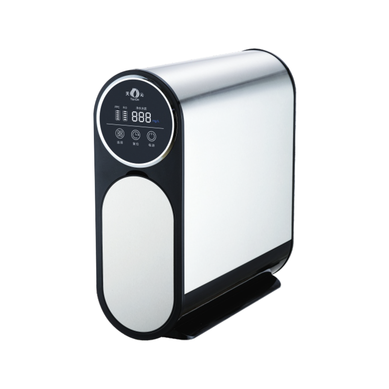 TQ-R03 Stainless Steel Booster Double Water Full Effect RO Water Purifier Cat:Stainless Steel Ro System
TQ-R03 Stainless Steel Booster Double Water Full Effect RO Water Purifier is a household water purification device that combines efficient water purif...
See Details -
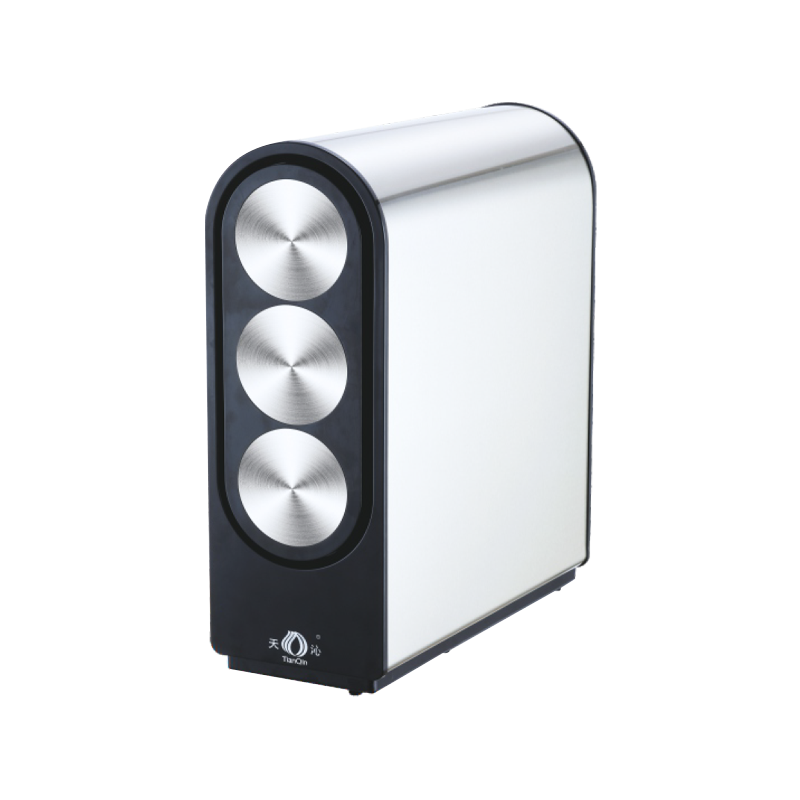 TQ-R05 Multifunctional Water Purification Source RO Water Purifier Cat:Stainless Steel Ro System
The TQ-R05 Multifunctional Water Purification Source RO Water Purifier is an advanced, versatile water purification solution designed for households a...
See Details -
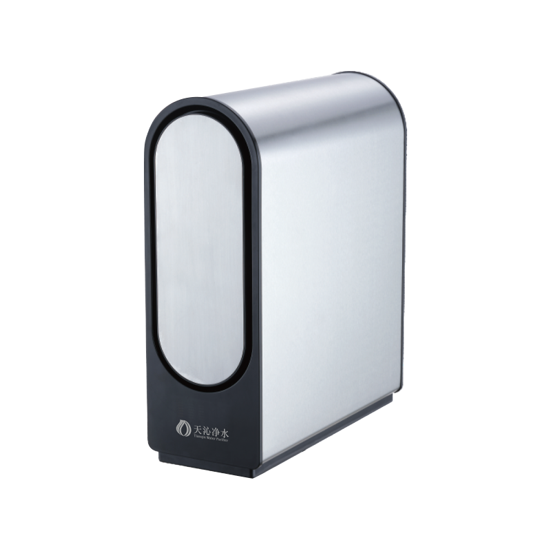 TQ-R06 Stainless Steel Environmentally Friendly RO Water Purifier Cat:Stainless Steel Ro System
The TQ-R06 Stainless Steel Environmentally Friendly RO Water Purifier combines advanced RO filtration technology, durable stainless steel housing, and...
See Details -
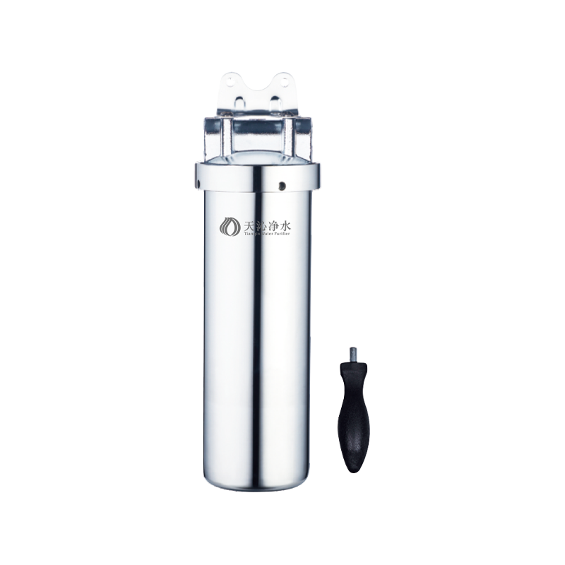 Stainless Steel Pure Double Water Pipe Water Purifier Cat:Stainless Steel Pipeline Water Purifier
The Stainless Steel Pure Double Water Pipe Water Purifier is an advanced water purification system designed to provide dual-mode purified water with e...
See Details -
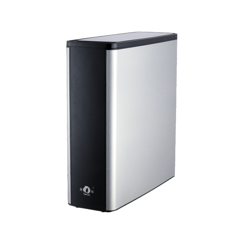 TQ-R08 Stainless Steel High-Flow RO Water Filter Cat:Stainless Steel Ro System
The Stainless Steel High-Flow RO Water Filter (TQ-R08) provides a powerful and effective solution for purifying drinking water, combining advanced rev...
See Details


 +86-0574-62381077/62386875

how does the ro membrane work: Applications, Selection Criteria, and Practical Guidance
Turn on the tap of a reverse osmosis system and the water that comes out has passed through a barrier whose pores are measured in fractions of a nanometre. That barrier is the RO membrane, and it is the reason the technology can strip out dissolved salts, metals and many other contaminants that ordinary filters let straight through. Everything else in the system — the sediment cartridge, the carbon block, the pump, the storage tank — exists either to keep that membrane healthy or to make the water it produces pleasant to drink.
This article walks through how the RO membrane actually works: what it is made of, what happens at its surface, why it needs a constant flow of reject water, and which conditions let it perform at its best. Once the mechanism is clear, the design choices inside a household or commercial system stop looking arbitrary.
Content
- 1 Osmosis, and What Makes It Reverse
- 2 Inside the Membrane: A Very Thin Layer Doing the Work
- 3 What Happens to Water and Contaminants at the Surface
- 4 Cross-Flow, Recovery and Why the Membrane Must Flush
- 5 The Conditions a Membrane Needs to Perform
- 6 How the Membrane Fits Into a Complete System
- 7 Reading the Signs: When a Membrane Is Tired
- 8 Matching the Membrane to the Job
Osmosis, and What Makes It Reverse
Osmosis happens whether or not anyone is paying attention. Place a semipermeable barrier between two bodies of water — one dilute, one salty — and water will cross toward the salty side until concentrations even out or the rising head of liquid stops it. The pressure required to hold that flow back is called osmotic pressure, and it scales with how concentrated the salty side is. Brackish water might exert one or two bar of osmotic pressure; seawater can approach twenty-five.
Reverse osmosis overwhelms that natural tendency. A pump raises the feed pressure above the osmotic pressure of the incoming water, and water molecules are pushed from the concentrated side across the barrier to the clean side. Nothing is boiled and nothing is chemically bound; the separation is mechanical at a molecular scale. In a domestic unit the operating pressure usually sits somewhere between roughly 40 and 80 psi, which is why systems installed where line pressure is weak often add a booster pump rather than simply accept sluggish output.
Inside the Membrane: A Very Thin Layer Doing the Work
The membranes used in water treatment today are almost always thin-film composite structures, built from three layers that each do a different job. A polyester nonwoven web at the bottom gives the sheet its mechanical strength. Above it sits a porous polysulfone support, perhaps forty micrometres thick, which provides a smooth bed for the layer that matters. On top of that is a polyamide active layer of roughly 0.2 micrometres — the dense, cross-linked skin where salt rejection actually happens.
That active layer is tight enough that hydrated ions struggle to pass, and it carries a slight negative surface charge that repels anions such as chloride and sulfate. Water molecules, small and uncharged, slip through far more readily than the dissolved species around them.
A flat sheet is awkward to package, so manufacturers wind the membrane into a spiral element. Two membrane sheets are glued on three edges around a permeate spacer to form an envelope. Feed spacers separate the envelopes, and the whole stack wraps around a perforated central tube. Feed water enters at one end and travels along the element; the portion that passes through the membrane spirals inward through the permeate spacer and collects in the central tube, while the remainder continues along the feed channel and leaves as concentrate.
What Happens to Water and Contaminants at the Surface
Rejection is not a single screening effect. Three mechanisms work together. Size exclusion keeps larger molecules and hydrated ions from entering the polymer free volume. Charge repulsion pushes back ions of the same sign as the membrane surface, which is why a negatively charged polyamide layer rejects chloride and sulfate better than it rejects some neutral species. On top of that, water and solutes diffuse through the dense layer at very different rates, so even molecules small enough to enter do not necessarily emerge on the other side in meaningful quantities.
The practical result is a permeate stream that is dramatically lower in dissolved solids than the feed. Two important exceptions are worth remembering. Dissolved gases such as carbon dioxide pass through relatively easily, which is why permeate from a household system can be slightly acidic and why some installations add a remineralisation or pH correction stage. Free chlorine is another: it is not well rejected, and over time it oxidises the polyamide layer, which is the reason a carbon prefilter sits ahead of the membrane in almost every well-designed system.
| Contaminant group | Typical rejection | Practical note |
|---|---|---|
| Dissolved salts (sodium, chloride, hardness) | 95–99% | Core strength of the process |
| Heavy metals (lead, arsenic in ionic form) | 96–99% | Depends on valence and speciation |
| Nitrate | 85–95% | Lower than chloride; monitor if relevant |
| Bacteria, protozoa, viruses | Above 99% | Rejection, not disinfection |
| Free chlorine | Low, and damaging | Remove upstream with carbon |
| Dissolved gases (CO2) | Low | May need pH adjustment after treatment |
Cross-Flow, Recovery and Why the Membrane Must Flush
An RO membrane is not a dead-end filter. If all the feed water were forced through the sheet, rejected salts would pile up on the surface within hours, osmotic pressure would climb and production would collapse. Instead the element is run in cross-flow: one portion of the feed passes through as permeate, while the rest sweeps along the membrane surface and carries the rejected salts away to drain.
The share that becomes permeate is called recovery. Household systems commonly run at around 25 to 50 percent, limited by a flow restrictor or an automatic flush sequence; larger commercial systems push higher, but only when scaling risk has been properly addressed. When recovery is pushed too far, calcium carbonate and sulfate begin to crystallise on the surface, a problem known as scaling. Long before that point, salts concentrate in the thin layer next to the membrane — concentration polarisation — which raises the effective osmotic pressure and quietly reduces flux. Turbulent feed spacers and adequate cross-flow velocity are what keep that boundary layer in check.
The Conditions a Membrane Needs to Perform
A polyamide membrane is durable, but it is not indifferent to its surroundings. The variables that matter most are these:
- Applied pressure. Net driving pressure is feed pressure minus osmotic pressure minus pressure drop. If it falls too low, both output and rejection suffer.
- Temperature. Warmer water flows more freely — flux typically changes by roughly three percent per degree Celsius — but warmer water also lets more solute through, so output and quality move in opposite directions.
- pH. Polyamide tolerates a wide band in continuous operation, commonly quoted as roughly 4 to 11, with short-term cleaning excursions permitted outside that. Sustained extremes hydrolyse the layer.
- Oxidants. Chlorine, chloramine and ozone attack the active layer. Keep free chlorine close to zero at the membrane inlet, using carbon or a reducing agent.
- Pretreatment. Sediment filtration, chlorine removal and, where hardness is high, softening or antiscalant dosing protect the element. Turbidity and silt density index are the numbers to watch.
- Recovery versus scaling risk. Higher recovery saves water but concentrates the feed. The safe balance depends on the water analysis, not on a fixed rule of thumb.
How the Membrane Fits Into a Complete System
Once you know that the membrane does the separating and that it dislikes chlorine, scale and debris, the order of components in a reverse osmosis system makes complete sense:
- A sediment prefilter captures rust, sand and pipe debris that would otherwise clog the feed channel.
- A carbon prefilter removes chlorine and many organic compounds before they can reach the polyamide.
- A booster pump lifts feed pressure into the working range when line pressure is insufficient.
- The membrane element performs the separation, with a flow restrictor or flush valve managing the concentrate stream.
- A post-carbon polisher improves taste and removes any residual odour picked up from the tank or tubing.
- Storage and delivery — a pressure tank or a tankless on-demand arrangement — determine how much water is available at the tap.
The membrane rewards good housekeeping upstream. Every cartridge in front of it exists to extend its working life, and a system that is easy to service tends to be a system that performs consistently for years rather than months.
TQ-R08 Stainless Steel High-Flow Reverse Osmosis Water FilterA stainless steel high-flow RO purifier with 400G–800G membrane options, self-priming pressurization and LED filter-life display for high-consumption homes or small offices.View Product →Reading the Signs: When a Membrane Is Tired
Membranes rarely fail without warning. The usual story is a gradual decline in permeate flow at unchanged pressure and temperature, a slow rise in the total dissolved solids of the product water, or an increasing pressure drop between feed and concentrate. Fouling from sediment and organics, scaling from hardness, and oxidation from chlorine each leave a slightly different fingerprint, and the response differs accordingly: better pretreatment, a cleaning cycle, or replacement of the element.
If you are troubleshooting a stainless steel system, our practical maintenance guide for stainless steel reverse osmosis systems walks through the routine checks in more detail. A simple habit — recording flow and product water quality every few months — turns guesswork into a clear trend line.
Matching the Membrane to the Job
Households That Want Water on Demand
Tankless designs run the membrane only when someone opens the tap, which avoids storing permeate for hours and keeps the footprint small under a counter. The trade-off is that the pump and membrane must handle intermittent starts, so a stable pressure supply and a well-matched prefilter train matter more than raw membrane area.
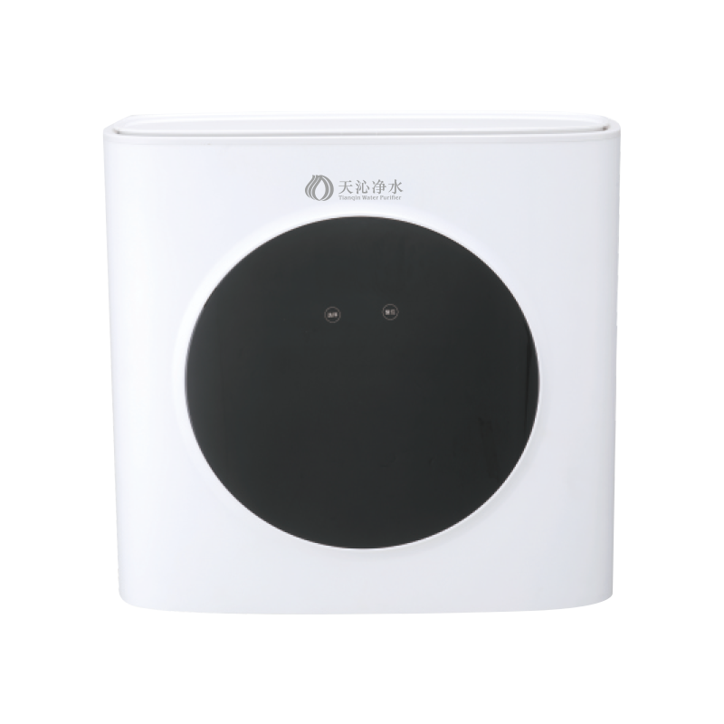 TQ-R14 High-Efficiency Tankless Reverse Osmosis Water PurifierTankless RO drinking-water purifier with 400G–600G membrane options, 1.5 L/min net flow, LED filter-life prompt and no pressure bucket.View Product →
Commercial Kitchens, Offices and Waiting Areas
At commercial scale the membrane is asked to produce continuously rather than occasionally. That shifts the priority towards pretreatment capacity, recovery control and a distribution stage that can hold hot or cold water through a busy day. A stepped heating arrangement with a generously sized stainless steel tank is one way to keep a queue of people served without the membrane being cycled on and off all morning.
 TQ-T2 30L Stainless Steel Commercial Reverse Osmosis Drinking MachineA commercial RO drinking-water machine with 30L 304 stainless steel tank, step heating, automatic water production and heating for peak demand.View Product →
The RO membrane is a simple idea executed with unusual precision: apply enough pressure, give the water somewhere to go, and keep the surface clean enough to keep working. Everything else in a purification system is support cast. Get the supporting stages right and the membrane will quietly do its job for a long time.
We have been building stainless steel water purification equipment since 1998, and much of what we have learned sits in the details of pretreatment, housings and serviceability. You can read more about our workshop, our team and how we approach manufacturing if you would like to see how that experience translates into hardware.
-
 Tel: +86-0574-62381077/62386875
-
 E-mail: leozhanglei@nbtianqin.net
-
 Add: Wuma Industrial Zone, Lubu Town, Yuyao City, Zhejiang Province, China.
Copyright © 2024 by Yuyao Tianqin Water Purification Equipment Co..Ltd.
All Rights Reserved.
 Wholesale Water Purifier Manufacturers

