 English
 中文简体
-
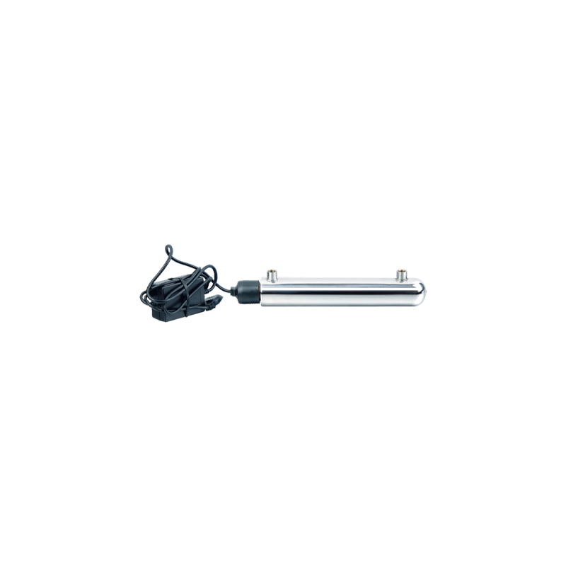 UV11W High-efficiency Intelligent UV Water Sterilizer Cat:Ultraviolet Water Sterilizer
The UV11W High-efficiency Intelligent UV Water Sterilizer is an advanced water purification system that offers convenience and reliability. This steri...
See Details -
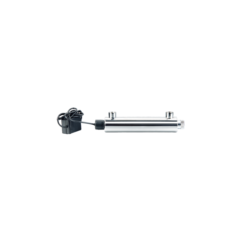 UV16W-A Household Stainless Steel UV Water Sterilizer Cat:Ultraviolet Water Sterilizer
The UV16W-A Household Stainless Steel UV Water Sterilizer is an innovative solution for ensuring safe and pure water in your home. Designed with durab...
See Details -
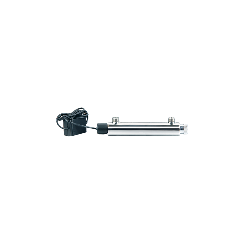 UV16W-B 304 Stainless Steel Water Purifier Ultraviolet Water Sterilizer Cat:Ultraviolet Water Sterilizer
UV16W-B 304 Stainless Steel Water Purifier Ultraviolet Water Sterilizer is an efficient water treatment equipment based on advanced ultraviolet disinf...
See Details -
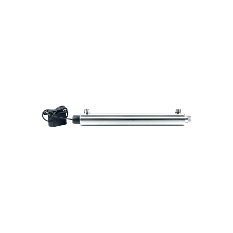 UV25W Stainless Steel Ultrafiltration Pre-Filtration UV Sterilizers For Water Cat:Ultraviolet Water Sterilizer
UV25W Stainless Steel Ultrafiltration Pre-Filtration UV Sterilizers For Water uses high-quality stainless steel materials, which have superb corrosion...
See Details -
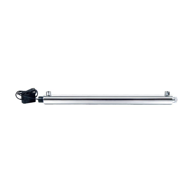 UV30W-55W Automatic Ultraviolet Sterilizer UV Filtration For Drinking Water Cat:Ultraviolet Water Sterilizer
The core advantage of UV30W-55W Automatic Ultraviolet Sterilizer UV Filtration For Drinking Water lies in its efficient and rapid disinfection capabil...
See Details -
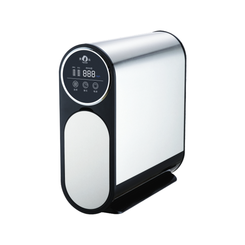 TQ-R03 Stainless Steel Booster Double Water Full Effect RO Water Purifier Cat:Stainless Steel Ro System
TQ-R03 Stainless Steel Booster Double Water Full Effect RO Water Purifier is a household water purification device that combines efficient water purif...
See Details -
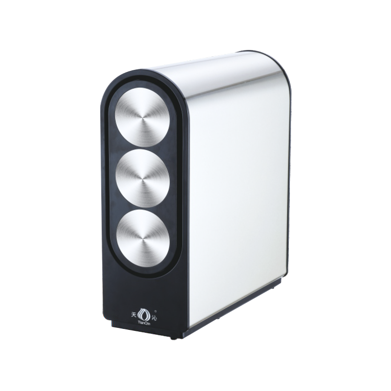 TQ-R05 Multifunctional Water Purification Source RO Water Purifier Cat:Stainless Steel Ro System
The TQ-R05 Multifunctional Water Purification Source RO Water Purifier is an advanced, versatile water purification solution designed for households a...
See Details -
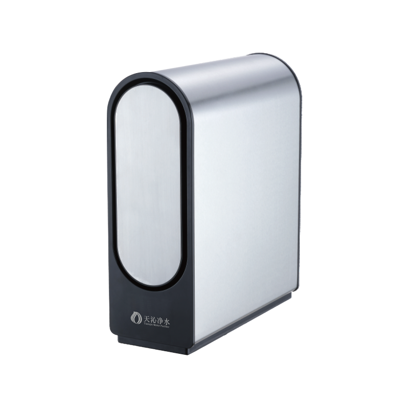 TQ-R06 Stainless Steel Environmentally Friendly RO Water Purifier Cat:Stainless Steel Ro System
The TQ-R06 Stainless Steel Environmentally Friendly RO Water Purifier combines advanced RO filtration technology, durable stainless steel housing, and...
See Details -
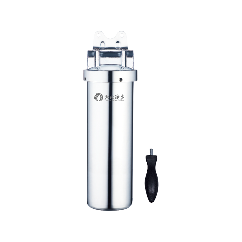 Stainless Steel Pure Double Water Pipe Water Purifier Cat:Stainless Steel Pipeline Water Purifier
The Stainless Steel Pure Double Water Pipe Water Purifier is an advanced water purification system designed to provide dual-mode purified water with e...
See Details -
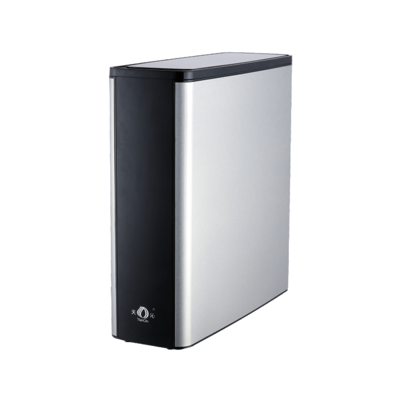 TQ-R08 Stainless Steel High-Flow RO Water Filter Cat:Stainless Steel Ro System
The Stainless Steel High-Flow RO Water Filter (TQ-R08) provides a powerful and effective solution for purifying drinking water, combining advanced rev...
See Details


 +86-0574-62381077/62386875

How Does a Water Softener Work? A Clear Diagram Walkthrough for Homeowners
Most water softener diagrams look more complicated than the process they describe. The drawing usually shows two tanks, a control valve, and a set of arrows for service flow and regeneration. Once you separate those two modes, the diagram becomes a practical map: hard water goes in, calcium and magnesium are held on resin beads, and soft water goes out. The brine tank and drain line explain how the resin is cleaned and reused.
Content
- 1 What the diagram shows at a glance
- 2 The service flow: from hard water to soft water
- 3 The regeneration cycle: the second half of the diagram
- 4 What the diagram does not show
- 5 Softener, filter, and RO: three different boxes in a whole-house drawing
- 6 Sizing and installation clues in the diagram
- 7 Common mistakes when reading a softener diagram
- 8 When the diagram matches your water problem
What the diagram shows at a glance
A typical diagram labels the raw water inlet, an optional prefilter, the resin tank, the brine tank, the control valve, a riser tube and distributor, the treated water outlet, and a drain line. The resin tank is the working vessel. The brine tank is the salt storage and regeneration vessel. The control valve is the traffic director that changes the flow path between service and regeneration.
| Diagram label | Function in the drawing | Why it matters |
|---|---|---|
| Raw water inlet | Brings hard water into the system | Flow rate and pipe size set the practical capacity. |
| Resin tank | Holds the ion exchange resin bed | Hardness removal happens here, not in the brine tank. |
| Brine tank | Stores salt and makes brine for regeneration | It is used periodically, not during normal service flow. |
| Control valve | Switches between service, backwash, brine draw, rinse, and refill | Valve settings determine whether the cycle completes properly. |
| Riser tube and distributor | Collects soft water and spreads flow through the resin | Uneven flow can reduce exchange efficiency. |
| Treated water outlet | Sends soft water to the home or process | A bypass or blend valve may be fitted here. |
| Drain line | Carries backwash and rinse water to waste | It must handle the flow without restriction. |
Read the drawing in two passes. First follow the service arrows, then follow the regeneration arrows. In many diagrams the same vessel appears twice with different flow paths, which is why the image can feel crowded.
The service flow: from hard water to soft water
During service, the control valve sends water down through the resin bed. The diagram may show the inlet at the top and the outlet at the bottom, or the reverse, depending on the valve design. The important part is the contact between water and resin.
- Hard water enters the resin tank.
- As it moves through the bed, calcium and magnesium ions attach to the resin.
- The resin releases sodium or potassium ions in exchange.
- Soft water collects at the bottom through the riser tube and leaves the tank.
- The flow continues until the resin nears exhaustion and the valve starts regeneration.
This is ion exchange, not filtration. The resin does not trap particles like a sediment screen. It swaps one set of dissolved ions for another. That is why a softener is good at hardness and not a substitute for a sediment filter, carbon filter, or reverse osmosis membrane.
The regeneration cycle: the second half of the diagram
After a set volume or time, the control valve moves the system into regeneration. The diagram often shows a brine line from the brine tank to the control valve, a drain line, and a refill path. The sequence usually runs like this:
- Backwash: water runs upward to loosen the bed and flush out trapped debris.
- Brine draw: concentrated salt brine is pulled into the resin tank.
- Contact and exchange: the high-sodium brine displaces calcium and magnesium from the resin.
- Slow rinse: remaining brine is pushed through the bed.
- Fast rinse: the bed is rinsed to remove excess salt.
- Refill: water returns to the brine tank to make brine for the next cycle.
The brine tank is not the resin tank. In the drawing they are separate vessels connected by a small line. The salt sits in the brine tank, and the resin stays in the pressure vessel. Regeneration is intermittent; soft water service continues between cycles. That distinction clears up one of the most common misreadings of the diagram.
What the diagram does not show
A process diagram is not a water test. It rarely shows hardness level, iron, manganese, sediment load, chlorine, or the flow rate your home actually needs. Those details decide whether a softener alone is enough. Visible sediment can foul the resin bed, and chlorine can shorten the life of some resins. In a whole-house drawing, a prefilter is often placed ahead of the softener for that reason.
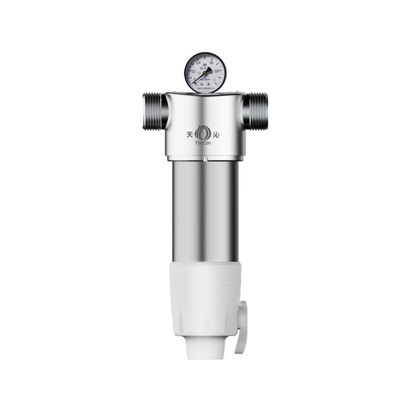 TQ-QZ02 Stainless Steel Water Pre-FilterA 40 μm stainless-steel prefilter for whole-house setups, protecting downstream softeners and filtration equipment from sediment and clogging.View Product →
For that first line of defense, a stainless-steel prefilter such as the TQQZ02 can sit ahead of the softener and catch the material you do not want reaching the resin. It does not soften water, but it protects the equipment that does.
The diagram also does not show that soft water is not automatically drinking water. A softener changes hardness, not microbiological safety or every dissolved contaminant. If the goal is cleaner drinking water at the kitchen tap, a reverse osmosis stage may be the next box on the drawing. Our reverse osmosis guide walks through that membrane flow.
Softener, filter, and RO: three different boxes in a whole-house drawing
It helps to label the boxes by job rather than by size. A softener is an ion exchange unit. A sediment or carbon filter is a physical and chemical reduction step. A reverse osmosis unit is a membrane separation step. They can work together, but they are not interchangeable.
- Water softener: targets calcium and magnesium; uses salt and regeneration; does not remove all contaminants.
- Sediment or carbon filter: catches particles, reduces chlorine, taste, and odor; does not remove hardness.
- Reverse osmosis: pushes water through a membrane; removes a wide range of dissolved solids; often installed at a point of use and paired with pre-filters.
When a drawing shows all three, the order matters. Prefiltration usually comes first, the softener protects downstream equipment from scale, and point-of-use purification handles drinking water. We have been building stainless-steel water equipment since 1998, and that whole-house view is part of how our company approaches the category.
Sizing and installation clues in the diagram
A useful diagram often shows pipe size, drain size, bypass valves, and electrical connections. These details matter as much as the resin tank. A softener needs enough flow to serve showers and appliances without a serious pressure drop. It also needs a drain that can accept backwash flow, and a bypass so you can isolate the unit for service.
If the drawing includes a whole-house train, a central carbon unit may sit before the softener to reduce chlorine and taste and odor, or after it as a polishing step, depending on the water test and the resin. Our TQZY3500/TQZY5000 central water purifier is designed for that kind of automatic, whole-house position, with intelligent automatic flushing and activated carbon filtration.
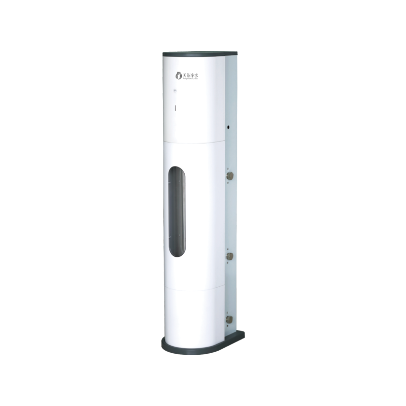 TQ-ZY3500/TQ-ZY5000 Automatic Flushing Central Water PurifiersWhole-house activated carbon purifiers with smart automatic forward and reverse flushing, available in 2 t/h and 3 t/h capacities.View Product →
Do not size a softener by tank height alone. Resin volume, salt setting, service flow, and regeneration frequency all work together. A larger tank with the wrong valve setting can underperform, and a small tank on a high-flow line can exhaust quickly. The diagram should be read with the spec sheet, not instead of it.
Common mistakes when reading a softener diagram
- Calling the brine tank the resin tank. They are separate, and salt does not belong in the resin vessel.
- Assuming regeneration is continuous. It is a periodic cycle; service flow is the normal state.
- Treating soft water as sterile water. It is lower in hardness, not automatically microbiologically safe.
- Forgetting the bypass. A bypass is not decoration; it lets you isolate the unit.
- Ignoring the prefilter. Sediment and chlorine can affect resin life and performance.
- Skipping the water test. Hardness, iron, and chlorine change the equipment plan.
When the diagram matches your water problem
Use the diagram as a checklist. If hardness is the main issue, the resin tank and brine tank are the key boxes. If water also carries sediment, chlorine, or iron, the drawing needs pretreatment. If the concern is drinking water at the tap, a point-of-use reverse osmosis or ultrafiltration stage may belong on the same page.
A simple hardness test and a clear look at the source water will tell you more than a generic diagram. From there, the drawing becomes specific: which valve, which resin volume, which prefilter, and which polishing step. The goal is not a complicated system. It is a system where every box has a job.
A water softener diagram is easiest to read when you follow the water in two directions: service flow through the resin, then regeneration flow through the brine tank. Once those paths are clear, the labels stop being clutter and start being a maintenance guide. If you are planning a whole-house setup, match the diagram to your water test first, then choose the equipment that fills each box.
-
 Tel: +86-0574-62381077/62386875
-
 E-mail: leozhanglei@nbtianqin.net
-
 Add: Wuma Industrial Zone, Lubu Town, Yuyao City, Zhejiang Province, China.
Copyright © 2024 by Yuyao Tianqin Water Purification Equipment Co..Ltd.
All Rights Reserved.
 Wholesale Water Purifier Manufacturers

